Installation Overview
The TDS-1 is a small box approximately 1.5 by 3 inches. It connects to the
car using a detachable wiring harness containing ten wires. Some of these
wires are optional; a minimal installation requires only six. Depending
on the model year of your ur-S car, it may be possible to make
most or all of these connections without splicing any factory wires. In
some cases, splices are necessary, but these can be done reliably and with
relative ease.
Before beginning, you should gather a few tools and materials:
- Radio removal tools
- Wire strippers
- Heat gun, pocket torch, or cigarette lighter (optional)
- Crimper (optional)
- Nut driver or ratchet
- Screwdriver, slotted
- Wire ties ("Zip ties")
- Heavy duty hook and loop fastener (Velcro) with adhesive (optional)
Additionally, there are a few parts from the Audi dealer which you
may need. This depends on the model year, and is discussed below. For
quick reference, here are the part numbers:
| Qty |
Audi # |
Description |
Used for |
Applies to |
| 1 |
000 979 118 |
Medium male terminal |
MAP sensor |
Cars w/o trip computer |
| 1 * |
000 979 117 |
Medium female terminal |
Display |
Cars w/o Gamma CC radio |
| 1 |
000 979 120 |
Large female terminal |
Display |
Cars w/o Gamma CC radio |
| * Two terminals required; part number contains two terminals |
In most parts of the installation, there will be more than one way
to proceed. This document will present only a few of these alternatives.
For instance, some may prefer to use butt crimps to make the required
splices, rather than using the included heat shrink tubing. This is
perfectly acceptable, as long as generally accepted principles of automotive
wiring are followed.
Installation time
Total installation time will vary, depending on how long
it takes to remove the relevant trim pieces, mount the TDS-1
box, and splice 6 to 10 wires.
As a rough estimate, figure this job will take two to four hours.
Finally, a note on neatness: I doubt anyone has ever regretted doing
too neat of a wiring job. I can say from experience that a sloppy
wiring job, rediscovered months or years later, can be embarassing
and inconvenient. It is worth the extra time to do it right in the
first place.
The TDS-1 Harness
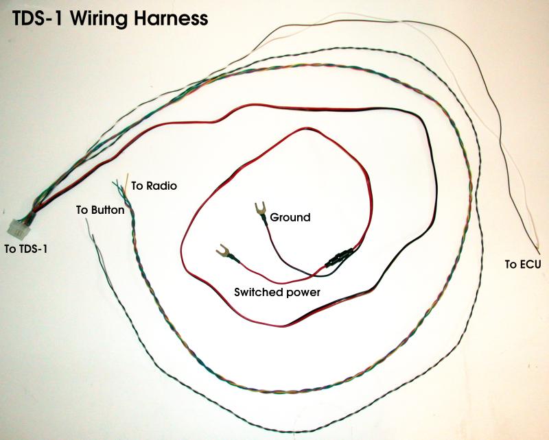
The TDS-1 uses a high quality 12 position connector to interface
with all car systems.
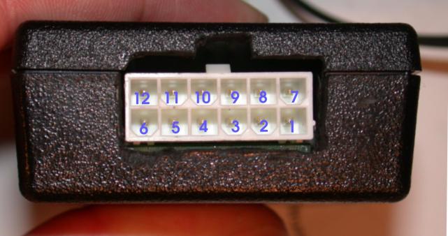
The following ten positions are used on the TDS-1:
|
Position
|
Connects to
|
Wire Color
|
Supplied Length
|
|
1
|
Ground
|
Black
|
72 in
|
|
2
|
Switched power, 12 volts <500mA (internally fused)
|
Red
|
72 in
|
|
3
|
User-interface button
|
Gray
|
68 in
|
|
6
|
From radio, pin T10/1 (green)
|
Orange
|
63 in
|
|
7
|
From radio, pin T10/2 (violet)
|
Blue
|
63 in
|
|
8
|
Intake air temperature sensor
|
White
|
42 in
|
|
9
|
Manifold Absolute Pressure (MAP) sensor
|
Brown
|
42 in
|
|
10
|
To instrument cluster, pin T14/8 (yellow) "enable"
|
Yellow
|
63 in
|
|
11
|
To instrument cluster, pin T14/4 (violet) "data"
|
Violet
|
63 in
|
|
12
|
To instrument cluster, pin T14/3 (green) "clock"
|
Green
|
63 in
|
Wire length
The TDS-1 harness is supplied with wires which are longer than necessary
in most cases. The wires should be cut to length in the car.
Making wire connections
You will need to make some splices between the TDS-1 harness and either
the terminals you bought from Audi or your car's wiring. These recommended
way to make these connections is by a Lineman's Splice,
insulated with the provided adhesive-lined heat shrink tubing.
Beginning the Installation
Mounting the TDS-1 control unit
The TDS-1 itself is quite small, and can be mounted in many places.
Perhaps the best location (and the one the wiring harness is designed
for) is the open space located above the engine computer (ECU). This is where
the transmission control unit is located on automatic transmission cars.
This space is accessed by pulling back the passenger footwell carpet and
removing the plastic cover of the ECU box. If your car has never been
"chipped", then the carpet may need to be cut. In that case, you may
prefer to mount the TDS-1 elsewhere.
Interior Disassembly
The following interior pieces must be removed for the TDS-1 installation:
- Radio (requires removal tools)
- Driver's side knee panel (for power)
- Passenger footwell carpet
- Passenger side kick panel
- Climate control head unit (95.5 S6 only)
Routing the wiring harness
From the mounting location, the wiring harness branches out in multiple
directions. You should route the wires before making any wire
connections. When running these wires, try to follow existing wire bundles. This will
help prevent you from unintentionally "wiring in" any interior parts
that you may someday have to remove. Zip ties or existing wire
retaining clips should be used to hold the new wire in place.
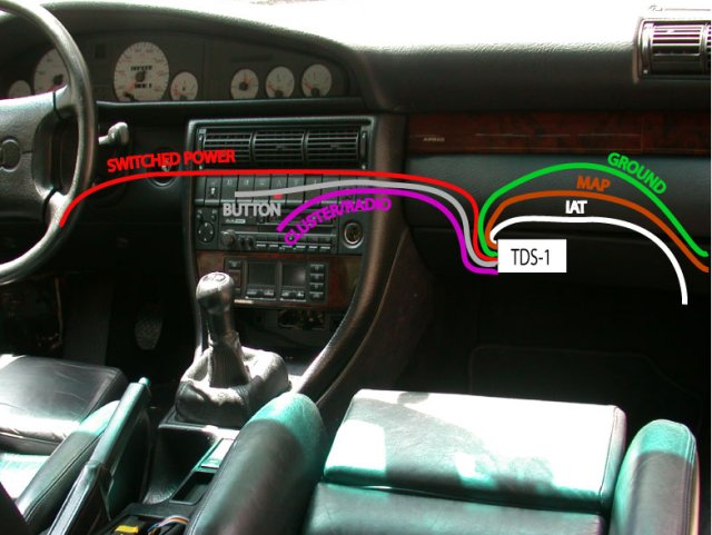
The cluster/radio and power wires should be routed behind the center console.
There is an opening in the upper left passenger footwell area where an
existing wire bundle runs from the ECU area to behind the center console.
The wires can be pushed through from the footwell, and, with the radio removed,
can be pulled through from the other side.
The power wire should then be pushed through the opposite side of the cluster
and on to the power distribution area under the steering wheel. As noted above,
you should be careful not to run the wires in such a way that interior pieces
which are not currently removed will be tethered by the wires.
Passenger-side connections
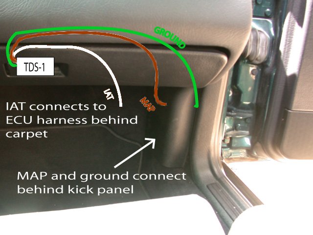
Interfacing To The MAP Sensor
The Manifold Absolute Pressure (MAP) sensor is used by the ECU to
monitor the amount of vacuum or boost present in the intake
manifold. This sensor is located within the metal ECU enclosure.
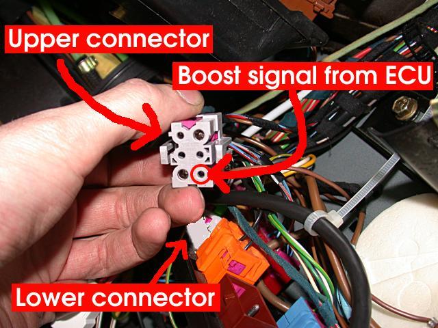
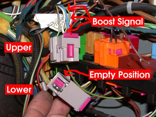
The MAP signal is output on pin 32 of the large ECU connector.
It is a yellow/blue striped wire and connects to position 1 of
connector T6d, gray, in Connector Station 2, in the passenger
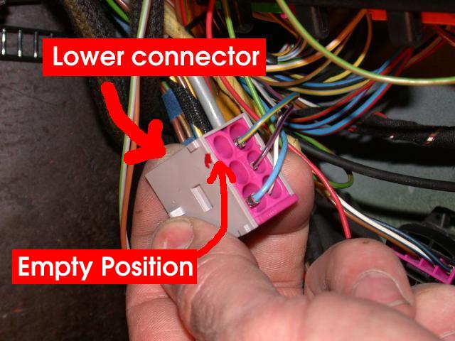
footwell. On cars without
a trip computer, the signal terminates at this connector, and
there is no mating contact in the opposite socket. On cars
with a trip computer, this signal continues on to
the rear of the instrument cluster.
The MAP signal wire runs from the ECU to one pin on the 6 pin
gray connector in the passenger footwell:

Interfacing to the Intake Air Temperature Sensor
One wire: white
This is an optional sensor. If this sensor is not connected,
the IAT modes will not be available, but the TDS-1 will
operate correctly otherwise.
The Intake Air Temperature (IAT) sensor allows the ECU to
monitor the charge air temperature, and adjust engine
parameters to prevent detonation when the IAT gets
excessively hot. This information is useful for the
driver as well, in order to monitor their intercooler
and turbocharger efficiency. For details on how this sensor
works, click here.
The IAT sensor connector in the engine bay has two positions. One of them
connects to ground inside the harness. The other
connects to the ECU on ECU connector position 44.
This connection is made directly via a brown with blue stripe wire.
Unfortunately there is no intermediate harness connector.
This brown/blue wire must be spliced to the white wire on the
TDS-1 for the IAT function to work.
The connection can be made in the engine compartment, or
in the wire bundle leading to the ECU.
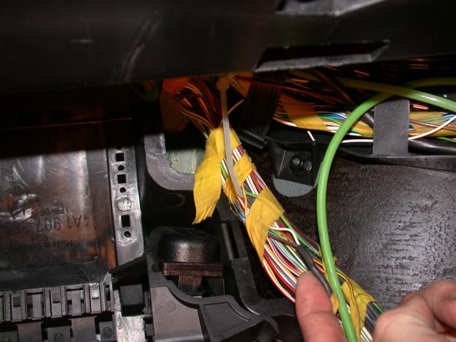
The easist place to make the connection is in the ECU harness.
You are looking for the brown with blue stripe wire.
You can see the other end of this wire on the IAT connector near
the throttle body.
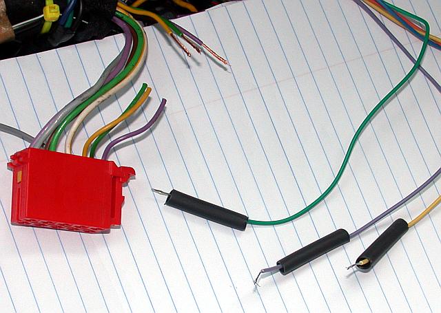
Te best way to make this connection is by making a
splice and heat shrinking it:
To make the splice without shortening the brown/blue wire relative
to the other wires in the harness, a piece of wire about 1.5
inches long should be used, in such a way that there are two
separate splices. The first is the brown/blue wire from the ECU to the
1.5 inch wire, the second is between the 1.5 inch wire, the white
wire to the TDS-1, and the brown/blue wire to the sensor in the
engine bay. A single piece of heat shrink can cover both splices,
as in the above picture.
An easier method is to use a "vampire tap", which are available
from electronics and auto parts stores. These are not watertight,
and would appear to be less reliable than the heat shrink method.
Interfacing To The Display
Five wires: violet, green, yellow, (orange), (blue)
The TDS-1 is designed to be inline between the factory radio and the
instrument cluster display. From the factory, the Audi instrument
cluster in the C4 cars can display the radio station and other
information transmitted by head units which support this feature.
The TDS-1
understands the protocol used by the radio and instrument cluster,
and can simultaneously transmit to the instrument cluster and
receive from the radio.
The connection from the TDS-1 to the instrument cluster is
required for the TDS-1 to operate. In most cases the best
way to connect these wires is by splicing into the radio
harness behind the radio. This requires radio removal
tools, which can be found at your local car stereo shop
or on eBay, among other places.
This diagram shows the splices necessary:
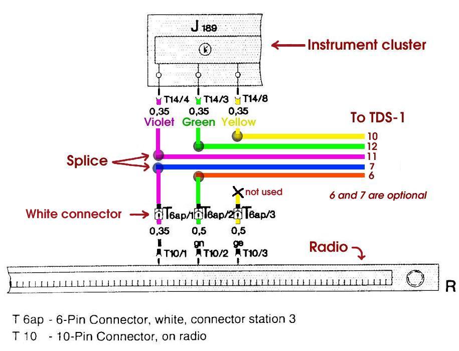
If you do not connect the orange
and blue wires, the radio station display will no longer be available, but the
TDS-1 will function correctly otherwise.
Carefully route the five wire bundle to the radio harness. When routing
the wire, be sure to route it under the bottom of the radio bracket,
and follow the factory harness. If you ever have to remove your
center console, you don't want it to be wired in by the TDS-1 wiring
harness.
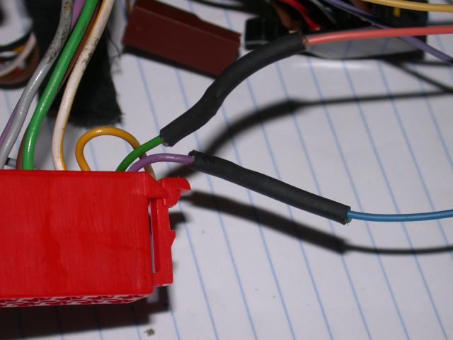
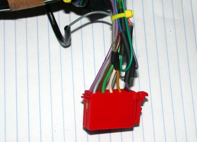
This red connector (T10) plugs into the back of the radio. The three
relevant wires are numbered 1-3. The numbering is as in the wiring
diagram excerpt above. Note that wire #2 is on the row of pins
farthest from the camera, while #1 and #3 are on the closer row.
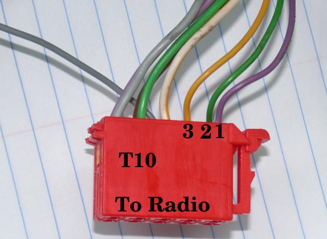
The wires from the TDS-1 wiring harness will be spliced into three
of the wires on the red connector:
The connections will be made using a Lineman's Splice and sealed with dual wall adhesive heat shrink tubing. Another method would be crimp style butt connectors, which are somewhat quicker, but bulkier.
Remember to put the wires through the tubing before making any connections.
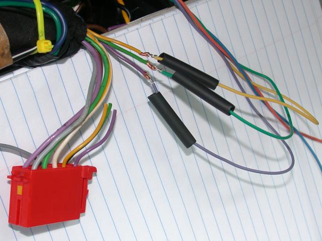
The result is durable and waterproof:
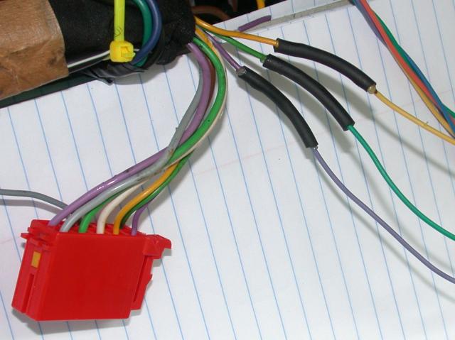
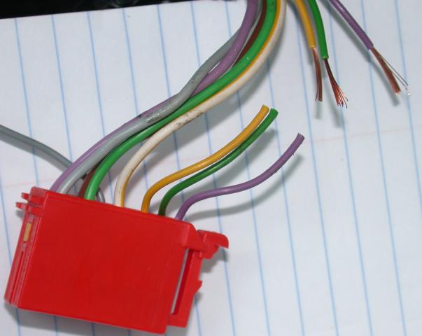
Now the wires from the radio to the TDS-1:
Only the violet and green wires connect to the TDS-1 harness:
The yellow wire end is covered with a small piece of heat shrink,
and the resulting wire bundle is tied with a zip tie.
Power Connections
Two wires: red and black
The TDS-1 must be connected to the switched power bus,
and to ground.
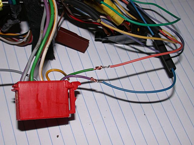
Ground wire
The black wire should be
connected to a convenient grounding point. There is
a grounding stud located behind the passenger-side kick
panel (look for the brown wires with ring terminals).
Power wire
The red wire should be connected to the switched power bus
underneath the steering wheel.
The supplied wiring harness includes an inline fuse holder on the red
positive wire and both red and black (ground) wires have spade lugs attached.
These spade lugs fit the #15 power stud, and the ground stud near the
passenger door.
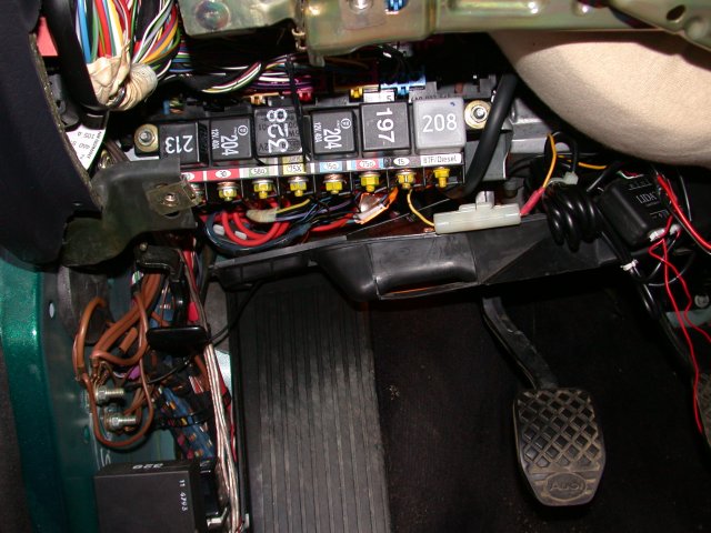
The power distribution panel is accessed by removing the
knee panel under the steering wheel. There are 5 10mm bolts
that must be removed. First remove the two on the horizontal
black plastic piece above the pedals:
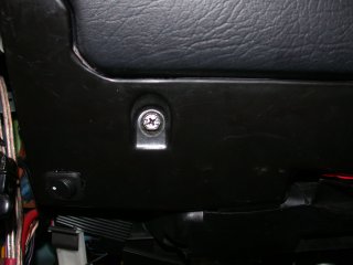
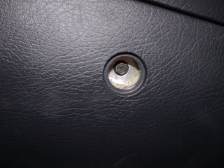
Then remove the two bolts behind the plastic plugs:
Finally there is a third bolt near the hood release that
must be removed.
Circuit #15 is the switched power circuit:
The TDS-1 power wire has a spade lug preattached. Carefully
route it to the #15 terminal. In this picture, it is connected
from the front for illustration purposes, but routing the wire rearward (toward
the front of the car) is preferred.
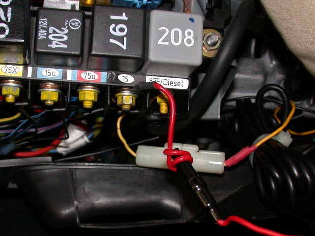
The red wire between the spade lug and the fuse should be very carefully
routed. This short piece of wire before the fuse is not protected
by the fuse and, if shorted to chassis ground, could cause a fire.
Consider zip-tying the unfused wire portion and the fuse to a nearby
wire bundle.
The TDS-1
has an internal fuse in addition to the inline fuse in the wiring
harness. The function of the external fuse holder is
to protect the power wiring itself against shorts. In the unlikely
event of a short circuit within the TDS-1 (due to extreme overvoltage or
some other fault), the internal fuse will prevent the TDS-1 from being
a hazard. It is your responsibility to determine whether the external
fuse is required in your particular installation. It is possible
to connect to the switched power bus on the passenger side, but this
is a deviation from the recommended installation procedure.
Interfacing to the User Interface Button
One wire: gray (plus ground: black)
The TDS-1 has multiple operation modes. A button is used
to select the active mode. Each press of the button
advances to the next mode. A long button press (> 2 seconds)
is used to enter and exit configuration mode.
The TDS-1 is not supplied with an external button.
There is a button mounted on the TDS-1 which operates
identically to an external button.
If you want to run the TDS-1 in only one mode
(i.e. peak boost mode), then an external button is not necessary.
The built-in button can be used to configure the TDS-1 and
select the desired mode at setup time, and the TDS-1 will
start up in that mode in the future, even when power is
disconnected for an extended period of time.
For most users, a a user-supplied button should be connected
to the TDS-1. This button must be a momentary, normally open
switch. Many different styles of switches of this type are
available at Radio Shack or other electronic component vendors.
It is also possible to use an Audi switch from a dealership
or junkyard, if you can find one with momentary contacts.
It is a matter of personal preference
which button is used and where it is mounted. A few suitable
switches and locations will be discussed.
Connecting the switch
The TDS-1 wiring harness contains a gray and a black wire twisted
together. These connect to the momentary, normally open pushbutton
of your choice. The black wire is connected to the TDS-1 ground
wire in the harness.
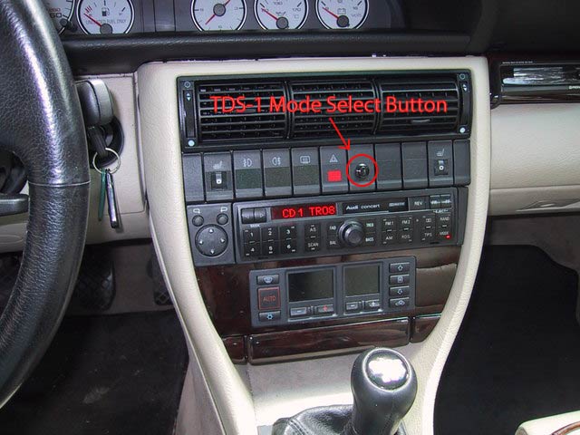
Suggested button locations and types
- Switch panel above radio
- Differential lock panel
- Retrofitted trip computer stalk?
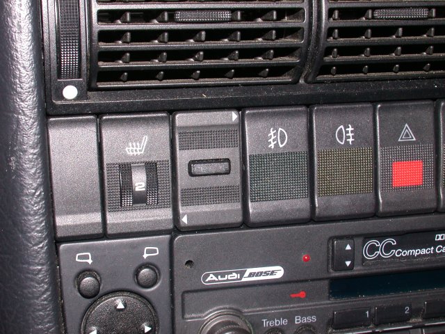
Example button installations
A generic Radio Shack switch mounted in a switch blank:
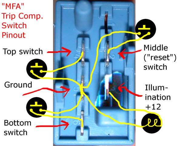
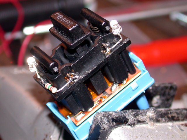
For the OEM look, a trip computer switch from a B3 or B4 80/90/CQ can be used:
See here for a schematic (I used the "reset" switch for the TDS-1).
See here for how to add LEDs to an old "MFA" trip computer switch.
Suggested switches
- Radio Shack #275-644
- Any momentary normally open pushbutton that you find aesthetically pleasing
Warning on installing illuminated switches
The TDS-1 wiring harness includes two wires for the switch: a gray wire for the switch signal,
and a black ground wire. The black ground wire should NOT be used if you are using an illuminated
switch like the "MFA" trip computer switch. If you do use this ground wire for an illuminatio
circuit, the current from the light bulb(s) or LEDs will
return through the TDS-1, potentially raising the TDS-1 local ground by a few millivolts, which
could be
enough to distort readings from the very sensitive analog-to-digital converters on the TDS-1. When using an
illuminated switch, you should not connect the black switch wire, and instead tap into a
ground point in the switch panel, such as on an adjacent switch. (You will need to tap in for
the illumination circuit anyway.)