Interfacing To The MAP Sensor
One wire: brown
The Manifold Absolute Pressure (MAP) sensor is used by the ECU to monitor the amount of vacuum or boost present in the intake manifold. This sensor is located within the metal ECU enclosure. Fortunately, due to the existence of a boost function in the trip computer on early cars, this signal is presented as an output by the ECU. This signal is conditioned ("buffered") such that connecting it to external equipment will not affect the readings made by the engine computer.
The MAP signal is output on pin 32 of the large ECU connector. It is a yellow/blue striped wire and connects to position 1 of connector T6d, gray, in Connector Station 2, in the passenger footwell. On cars without a trip computer, the signal terminates at this connector, and there is no mating contact in the opposite socket. On cars with a trip computer, this signal continues on to the rear of the instrument cluster.

The MAP signal wire runs from the ECU to one pin on the 6 pin
gray connector in the passenger footwell:

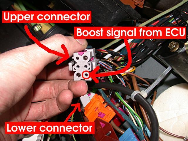
Note that there are TWO wires with both yellow and blue stripes. The one for the boost signal is slightly thicker, and connects to the smaller of the two pins. If you look closely, you can see that each pin on the connector is labeled. The boost signal is pin #1.
This is the upper half of the gray connector, where the boost
signal wire from the ECU terminates:
This is both connector halves, with the lower half removed
from the mounting bracket.
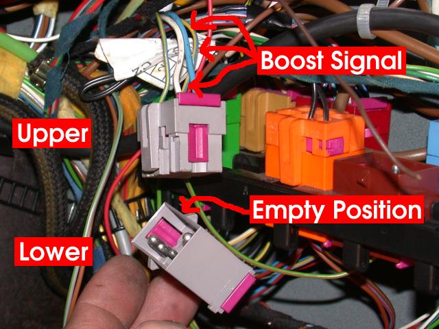
This is the lower half of the gray connector, with the
unused pin position marked where the boost signal terminates on
cars without the trip computer:
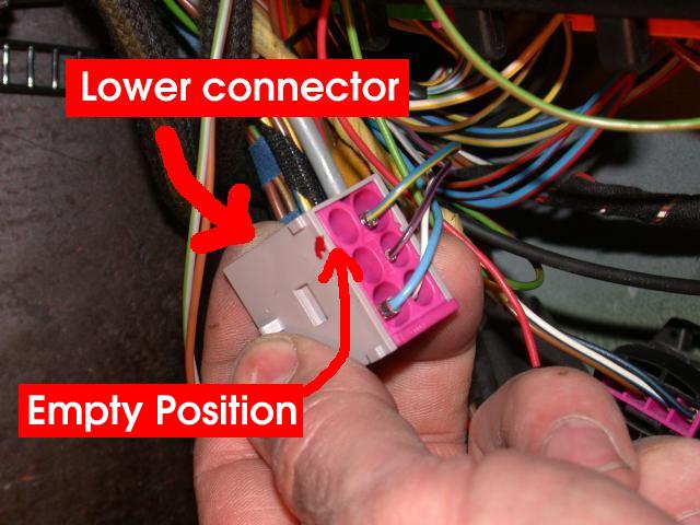
The MAP sensor connection can be made by adding a male pin to the lower connector in the marked position and connecting its pigtail to the brown wire of the TDS-1 wiring harness,