Note for installation into cars with Delta CC head unit
The display connections are different for later cars with the wide face Delta CC head unit. See these installation instructions for a '95.5 S6 if you have a Delta CC car.
Interfacing To The Display (Gamma CC head unit cars)
Five wires: violet, green, yellow, (orange), (blue)
The TDS-1 is designed to be inline between the factory radio and the instrument cluster display. From the factory, the Audi instrument cluster in the C4 cars can display the radio station and other information transmitted by head units which support this feature. The TDS-1 understands the protocol used by the radio and instrument cluster, and can simultaneously transmit to the instrument cluster and receive from the radio.
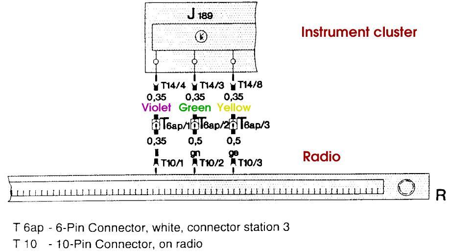
There are three signals connecting the radio to the instrument
cluster. As shown in this exerpt from the factory wiring diagram
(from 1994), the signals pass through Connector Station 3, which
is located behind the climate control unit.
The connection from the radio to the TDS-1 is optional. If you do
not have a Gamma CC radio installed, there is no need to connect
these wires. The TDS-1 will automatically detect that there is
no radio connected, and skip over the radio pass-through mode.
If you do not have a Gamma CC radio, you may wish to use the
95.5 instructions instead.
The connection from the TDS-1 to the instrument cluster is
required for the TDS-1 to operate. In most cases the best
way to connect these wires is by splicing into the radio
harness behind the radio. This requires radio removal
tools, which can be found at your local car stereo shop
or on eBay, among other places.
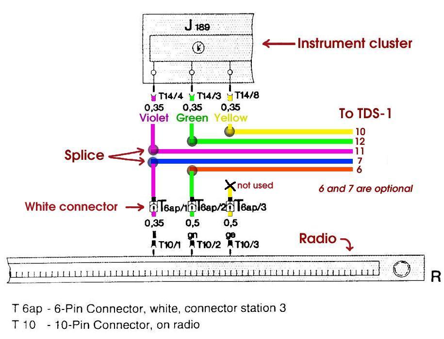
This diagram shows the splices necessary:
If you do not connect the orange
and blue wires, the radio-passthrough mode will not be available.
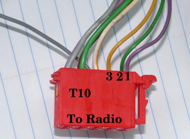
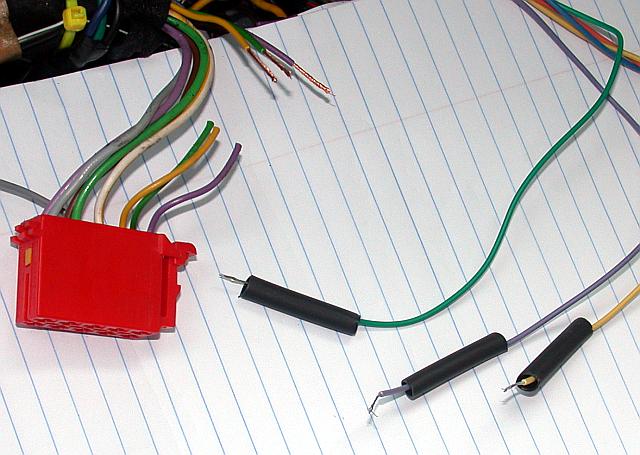
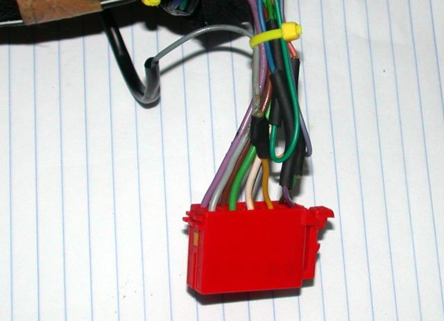
This red connector (T10) plugs into the back of the radio. The three
relevant wires are numbered 1-3. The numbering is as in the wiring
diagram excerpt above. Note that wire #2 is on the row of pins
farthest from the camera, while #1 and #3 are on the closer row.
The wires from the TDS-1 wiring harness will be spliced into three
of the wires on the red connector:
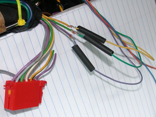
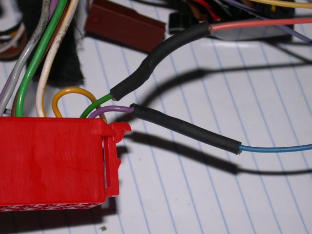
The connections will be made using a Lineman's Splice and sealed with dual wall adhesive heat shrink tubing. Another method would be crimp style butt connectors, which are somewhat quicker, but bulkier.
Remember to put the wires through the tubing before making any connections.
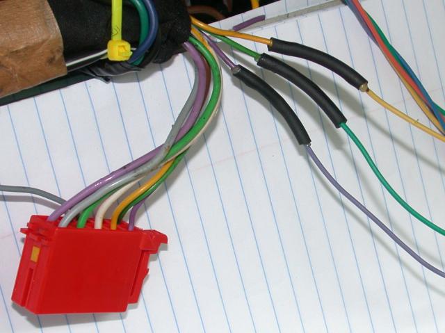
The result is durable and waterproof:
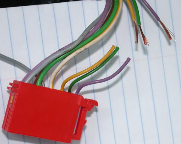
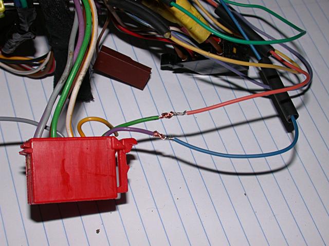
Now the wires from the radio to the TDS-1:
Only the violet and green wires connect to the TDS-1 harness:
The yellow wire end is covered with a small piece of heat shrink,
and the resulting wire bundle is tied with a zip tie.