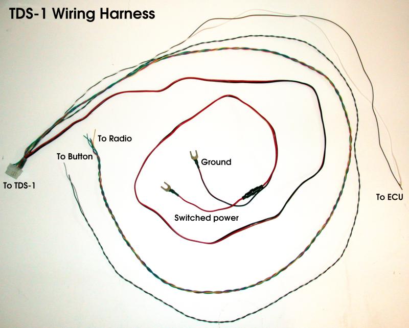
The TDS-1 Wiring Harness
The TDS-1 Connector
The TDS-1 uses a high quality 12 position connector to interface with all car systems.
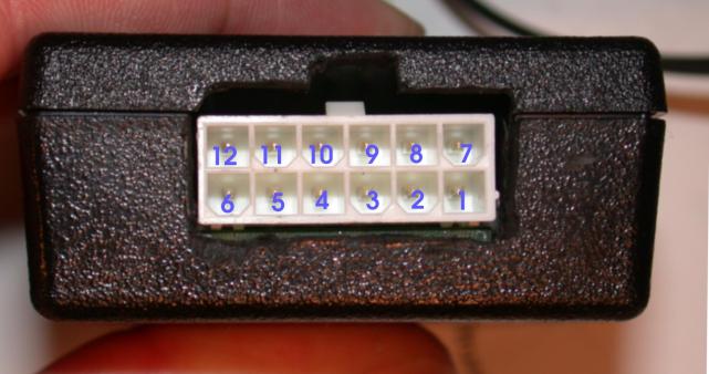
The following ten positions are used on the TDS-1:
| Position | Connects to | Wire Color | Supplied Length |
| 1 | Ground |
Black
|
72 in |
| 2 | Switched power, 12 volts <500mA (internally fused) |
Red
|
72 in |
| 3 | User-interface button |
Gray
|
68 in |
| 6 | From radio, pin T10/1 (green) |
Orange
|
63 in |
| 7 | From radio, pin T10/2 (violet) |
Blue
|
63 in |
| 8 | Intake air temperature sensor |
White
|
42 in |
| 9 | Manifold Absolute Pressure (MAP) sensor |
Brown
|
42 in |
| 10 | To instrument cluster, pin T14/8 (yellow) "enable" |
Yellow
|
63 in |
| 11 | To instrument cluster, pin T14/4 (violet) "data" |
Violet
|
63 in |
| 12 | To instrument cluster, pin T14/3 (green) "clock" |
Green
|
63 in |
Power connection
The TDS-1 has an internal 500mA fuse, in addition to the inline fuseholder (also with 500mA fuse) included in the wiring harness. Depending on where you choose to connect to the car's switched power circuit, you may or may not need the inline fuse. The purpose of the inline fuse is to protect the wiring in the case of a short before the TDS-1. If you tap into an already fused circuit, such as the "trunk popper" wire near the glove box, then you can safely omit the inline fuse. If you prefer to connect to the power distribution bolts underneath the driver's knee panel, then the inline fuse is necessary, because the power distribution bolts are before the fuse panel.
Wire length
The TDS-1 harness is supplied with wires which are longer than necessary in most cases. The wires should be cut to length in the car.